Servo power usage
Recently there was a
thread at the RunRyder forum on
power use. Most people with 60 machines found a total power use (including five digital
servos, governor, and the whole shit) of 2A.
AirWolfRC there presented a nice overview that I repeat here to save
it from getting lost in the annals of RR. The lower rows report
several values of my own machine, for an older analog setup and my current
all-digital setup in different flying styles.
name | Heli | Servos | Gyro | Govnr | Volts | mah/flt | min/flt | mah/min | Amps |
AirWolfRC | Raptor-50 | analog | GY-401 | 4.8 | 180 | 10 | 18 | 1.1 | |
BlueFronted | Vigor CS | 9402 | GY-601 | GV-1 | 4.8 | 500 | 20 | 25 | 1.5 |
Bob00 | Fury Extr. | 9252 | GY-601 | GV-1 | 275 | 8 | 34 | 2 | |
Dragon2115 | Fury Extr. | digital | CSM560 | GV-1 | 6.0 | 330 | 10 | 33 | 2 |
Eric | Fury Extr. | 9252 | GY-601 | GV-1 | 4.8 | 300 | 8 | 38 | 2.3 |
Gidday | Raptor-30 | 9252 | GY-401 | 4.8 | 243 | 13 | 19 | 1.1 | |
KCT | Fury Extr. | 8231 | JR-5000 | GV-1 | 4.8 | 290 | 8 | 36 | 2.2 |
Phil Cole | X-Cell 60 | 8231 | GY-601 | 4.8 | 2 | ||||
RaptorRecker | Fury Extr. | 9252 | 4.8 | 290 | 8 | 36 | 2.2 | ||
Sluggo | Fury Extr. | 9252 | GY-601 | GV-1 | 4.8 | 310 | 8 | 39 | 2.3 |
W.Pasman | Raptor 50 | 9250 tail, rest analog | Robbe 3D | 4.8 | 130 | 10 | 13 | 0.8 | |
W.Pasman(hover) | Raptor 50 | 9254,9250 | CSM560 | 5.1* | 220 | 12 | 18 | 1.1 | |
W.Pasman(3D flight) | Raptor 50 | 9254,9250 | CSM560 | 5.1* | 350 | 12 | 29 | 1.7 | |
JKos | Predator Gasser | all digital | JR 500T | GV-1 | 5.4* | 600 | 25 | 24 | 1.4 |
KTC (same thread) also did some interesting measurements on the power usage with his scope.
He used a JR 950S PCM receiver, JR 8231 on cyclic and pitch, JR 517 on throttle,
Futaba 401with 9253, and a 4.8V NiCd 1700 mAh pack.
In one experiment he loaded all servos to the max (static) and checked the voltage
at the battery (Figure 1). It showed to fluctuate quite heavily, and the voltage dropped
0.4 to 0.5V.
Figure 2 shows the noise amplified. It seems to me some 250Hz frequency
and quite clear steps in the noise, maybe
the servos are switching around this rate.
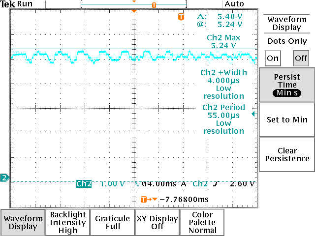
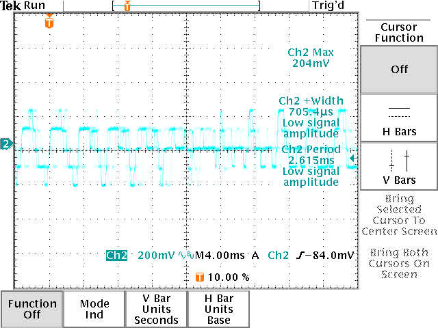
| Figure 1. Voltage behaviour with one servo loaded to it's maximum | Figure 2. detail view |
KTC also checked the internal resistance of a pack (0.0929 ohm) and 1 foot JR cable (0.1 ohm).
Note that this is significant, given a 2.2A average load and much higher peak loads!
Finally he measured some current use of components:
JR8231 servo: 15-35mA (idle), 850mA (max load).
601 gyro+9253 servo: 85mA (idle), 750mA (normal load) 1500mA (max load)
Donlynn measured the "newer Futaba h/d rx switch" and found 100mV when a
"couple of amps" (2.5?) is put through, giving around 0.04 Ohm for that switch.
Stephen Bell (SBR technical) did interesting measurements on accurately loaded servos.
He tested not the latest digital servos, but this overview is very instructional because
he also reported the servo centering behaviour, slop etc.
The load for these figures is 5 pounds (2.25kg) hanging from a 1/2 inch servo arm,
that makes 2.86kg.cm = 0.29 Nm = 40 oz.in. This must be quite close to the max load of most servos tested here.
In the table below he summarized his results.
For more details and tips on wiring installation visit the
scotia blade runners website.
Long ago I also did some measurements on the power usage of the R116FB receiver
(the one which comes with the FF6 transmitter) and servo's.
The measurements were done with an old needle current meter
(don't know the actual english word for this) to get the real effective current.
At that time I used 4 NiMH batteries.
NiMH has a higher internal resistance and for several people it seems to cause problems.
For instance I suspect it the cause of the woof&poof I had on with my raptor 30 (which disappeared
after I replaced the NiMH for NiCd's) and rckrzy1 on mentioned thread also finds low voltage on his voltspy after
only two flights.
Measurements with prehistoric analog needle current meter :-)
R116FB receiver: spec 20mA
Robbe 3D gyro: 40mA.
Futaba 9202 (analog), 3001 (analog) and 9250 (digital) servos:
idle 8mA (by spec), normal movements but unloaded: 100-150 mA; fast movements: 200mA.
Futaba 9202, heavily loaded (according to shop owner, also check the
FF8 manual): 600mA.
Because I used an analog meter here, these are effective currents; peak loads could be
significantly higher. Especially
with fast servos and gyros, loads may be very bursty.
During short peak loads battery voltage will drop much further
than during a continuous, not so high load. And even during peak loads you still need to stay
above 4.8V or maybe 4.6V to keep the system alive and working properly.
For instance, during normal hovering and smooth flying some 500mA is drawn
(after 4 15minute flights I had usually about 1200mAh left in my old 1700mAh cells).
Theoretically that would be enough for two hours or eight flights; however in practice
the gyro gets sloppy after only 6 flights and the seventh flight the tail hold gets really
marginal. This must be a combination of high resistance in the leads and high amperage
at moments the tail servo kicks in.
Concluding, you need ample reserves to stay in the safe zone, 1200mAh cells easily
might be too low for safe flying after only two flights. In practice, the usable capacity of
normal NiCd cells often is only 50%. For standard NiMH cells the usable capacity is even
lower (higher internal resistance = more power drop).
I recommend a voltage regulator with a 7.2V LiPo pack. Also possible would be
a standard pack with an an extra cell, and a regulator.
That eliminates the power dips and enables near-100% usable capacity,
say about 30% extra for safety.
If you go for NiCd cells, in my experience you need a 100% safety margin. Remember to always
use cells with low internal resistance (AirwolfRC recommends <10mOhm)
if you don't use a regulator.
The effective capacity also lowers when the batteries have to deliver extreme peak currents.
However for normal receiver packs, 2A is not an extreme peak so this should
not influence the effective capacity. The main problem with unregulated packs is an already marginal voltage
combined with internal resistance of the pack and the wires.